Blog / Hydraulic Cylinder Knowledge
Marine Crane Hydraulic Cylinders: Specification Review
JW’s hydraulic cylinder presentation includes a marine engineering crane application. For a new crane design or an existing cylinder replacement, the design drawings provide the basis for reviewing the cylinder’s function and interfaces within the equipment. This article explains how to use the presentation’s general specifications as a starting point for discussion with JW.
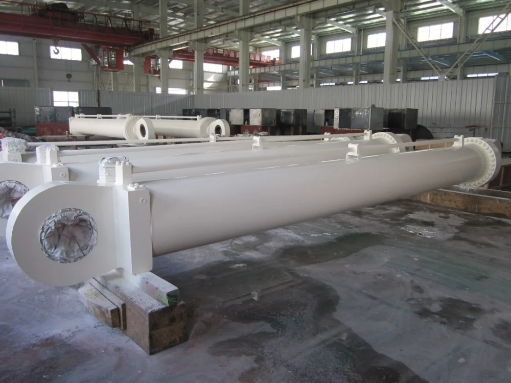
How to Read the General Specifications
The dimensions and pressure below are separate maxima listed in JW’s product presentation. They do not establish a cylinder that combines every maximum, and the material and surface-treatment entries describe alternatives. The temperature range also requires review for the selected configuration. A project-specific drawing and agreed technical specification define the final scope.
| Parameter | Reference information |
|---|---|
| Bore | 500 mm maximum, listed separately |
| Rod diameter | 400 mm maximum, listed separately |
| Stroke | 15,000 mm maximum, listed separately |
| Working pressure | 50 MPa maximum, listed separately |
| Working temperature | −50 °C to 100 °C, subject to configuration review |
| Cylinder material examples | Q345D, Q690E |
| Piston rod material examples | 40Cr (shown as 40CR in the source), 17-4PH |
| Rod surface-treatment examples | Chrome plating, nickel and chrome plating |
| Seal brands listed in the source | TRELLEBORG, PARKER, MERKEL; selection to be agreed |
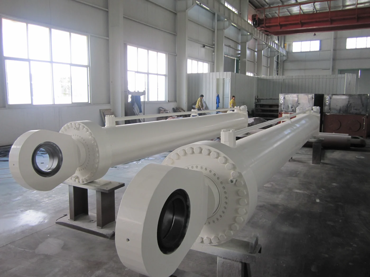
Application and Installation Review
The application topics below are engineering considerations, not a mandatory enquiry checklist. Your design drawings are the required starting point; operating conditions are helpful if available.
The drawing review covers the cylinder’s role in the crane mechanism, the equipment arrangement, design loads and movement. Working and peak pressure, stroke, mounting and alignment are reviewed against the drawing requirements. Operating information such as travel speed and duty cycle is helpful if available.
For a replacement, the design drawings provide the basis for reviewing mounting, connection dimensions and installation space. Pin and bearing details, closed and extended dimensions, ports and any valve or sensor interfaces are considered as part of that drawing review; the customer does not need to repeat them in a separate enquiry checklist.
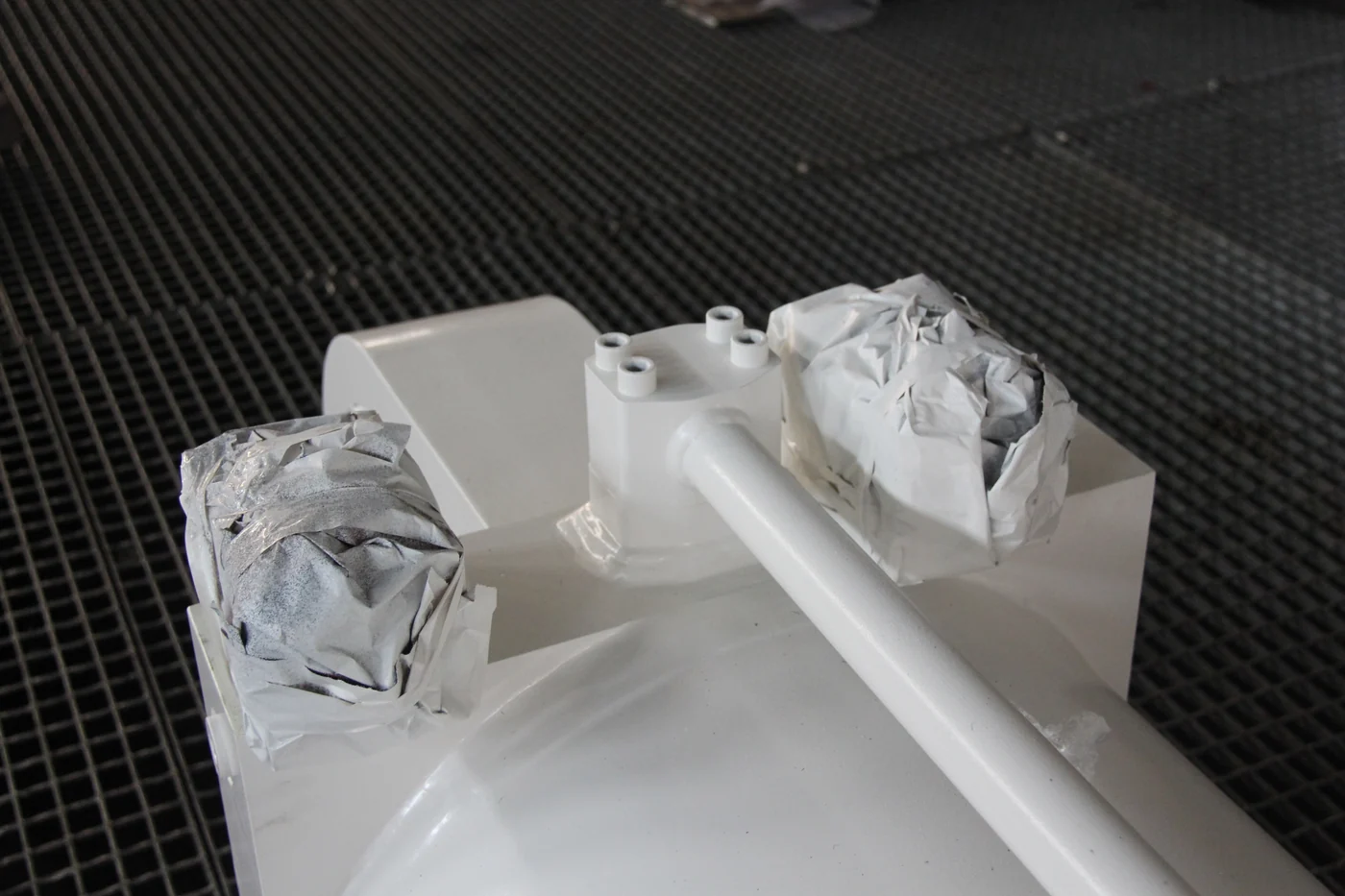
Environment and Acceptance Documents
Temperature, saltwater exposure and periods out of service can influence the rod material, surface treatment and sealing selection. Such operating information is helpful if available. Any classification-society or customer approval requirements are reviewed against the project scope; the general product presentation does not establish a project-specific approval.
Drawing approval, inspection records and test documentation are coordinated with the customer during the project review. For the broader review process, see JW’s engineering and quality planning information. You can also explore the custom hydraulic cylinder range before submitting the application details through Request a Quote.
Start Your Enquiry with Your Design Drawings
Enquiries are welcome in any format. Please email your design drawings to info@jwindustrialsolutions.com; drawings are required for quotation and manufacture. You do not need to repeat information already shown on the drawings. Operating conditions, including the working environment and frequency of use, are helpful if available. A dedicated specialist will follow up by email.
See the hydraulic cylinder order process: quotation from your drawings, order confirmation, detailed drawing approval, production, factory inspection and delivery documentation.
Send a cylinder enquiry or explore the JW hydraulic cylinder range.
Specification source: JW hydraulic-cylinder product presentation, marine application section. This article provides application and enquiry guidance. It does not identify a completed customer installation or replace the approved project drawing.